02) 6264.1921

ROHDE & SCHWARZ
HOME > 제조사별 > 파워 서플라이 > ROHDE & SCHWARZ
XG 1700 시리즈 파워서플라이
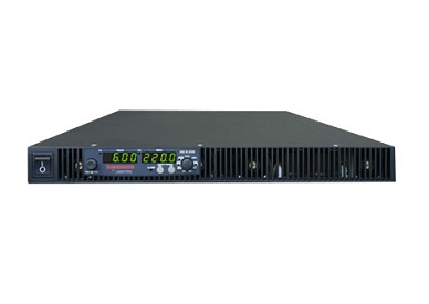
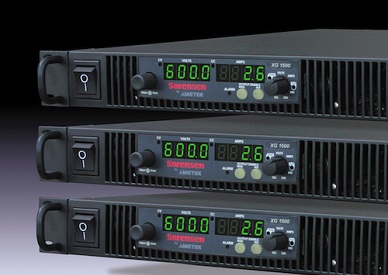
XG 1700 시리즈는 테스트, 생산, 실험실, OEM 및 품질 보증 어플 리케이션을 위해 설계된 산업용 프로그래머블 직류 전원 공급 장치입니다. 1700W, 1U 사이즈로 정전압, 정전류 모드, 자동 크로스 오버등 다양항 기능을 갖추고 있으며, 비용 대비 성능이 매우 우수한 장비입니다.
구매, 기술, 렌탈 문의 이성종 과장 010-4812-3482 / sjlee3482@gmail.com
특 징
- 자유로운 입력전압 (85~250VAC)
- 전력효율을 향상시키기위한 전력효율교정장치( PFC )
- Zero voltage "Soft Switching"
- 정전압,정전류, 정전력 작동
- 전면,후면 의 출력단
- 대기모드 기능
- 센스단자를 이용한 출력전압 보상
- LabVIEW? and LabWindows? drivers
- Over voltage protection
- Over temperature protection
- 무상 보증 기간 5년 사항
- 전력효율을 향상시키기위한 전력효율교정장치( PFC )
- Zero voltage "Soft Switching"
- 정전압,정전류, 정전력 작동
- 전면,후면 의 출력단
- 대기모드 기능
- 센스단자를 이용한 출력전압 보상
- LabVIEW? and LabWindows? drivers
- Over voltage protection
- Over temperature protection
- 무상 보증 기간 5년 사항
|
모 델 별 사 양 | |||
|
모 델 |
전 압 |
전 류 |
용 량 |
| XG 6-220 | 6 V | 220 A | 1330 W |
| XG 8-200 | 8 V | 200 A | 1610 W |
| XG 12-140 | 12 V | 140 A | 1690 W |
| XG 20-84 | 20 V | 84 A | 1690 W |
| XG 33-50 | 33 V | 50 A | 1690 W |
| XG 40-42 | 40 V | 42 A | 1690 W |
| XG 60-28 | 60 V | 28 A | 1690 W |
| XG 80-21 | 80 V | 21 A | 1690 W |
| XG 100-17 | 100 V | 17A | 1710 W |
| XG 150-11.2 | 150 V | 11.2 A | 1690 W |
| XG 300-5.6 | 300 V | 5.6 A | 1690 W |
| XG 600-2.8 | 600 V | 2.8 A | 1690 W |
| Sorensen XG 1700 Watt Specifications |
| Output Ratings | |||
| Model | Output Voltage¹ | Output Current² | Output Power³ |
| XG 6-220 | 6 V | 220 A | 1330 W |
| XG 8-200 | 8 V | 200 A | 1610 W |
| XG 12-140 | 12 V | 140 A | 1690 W |
| XG 20-84 | 20 V | 84 A | 1690 W |
| XG 33-50 | 33 V | 50 A | 1690 W |
| XG 40-42 | 40 V | 42 A | 1690 W |
| XG 60-28 | 60 V | 28 A | 1690 W |
| XG 80-21 | 80 V | 21 A | 1690 W |
| XG 100-17 | 100 V | 17A | 1710 W |
| XG 150-11.2 | 150 V | 11.2 A | 1690 W |
| XG 300-5.6 | 300 V | 5.6 A | 1690 W |
| XG 600-2.8 | 600 V | 2.8 A | 1690 W |
| Line Regulation | |||
| Model | Voltage (0.005% of rated output voltage +2 mV)4 |
Current (0.01% of rated output current +2 mA)5 | |
| XG 6-220 | 2.3 mV | 24 mA | |
| XG 8-200 | 2.4 mV | 22 mA | |
| XG 12-140 | 2.6 mV | 16 mA | |
| XG 20-84 | 3.0 mV | 10.4 mA | |
| XG 33-50 | 3.7 mV | 7 mA | |
| XG 40-42 | 4 mV | 6.2 mA | |
| XG 60-28 | 5 mV | 4.8 mA | |
| XG 80-21 | 6 mV | 4.1 mA | |
| XG 100-17 | 7 mV | 3.7 mA | |
| XG 150-11.2 | 9.5 mV | 3.12 mA | |
| XG 300-5.6 | 17 mV | 2.56 mA | |
| XG 600-2.8 | 32 mV | 2.28 mA | |
| Load Regulation | |||
| Model | Voltage (0.005% of rated output voltage + 2 mV)6 |
Current (0.02% of rated output current +5 mA)7 | |
| XG 6-220 | 2.3 mV | 49 mA | |
| XG 8-200 | 2.4 mV | 45 mA | |
| XG 12-140 | 2.6 mV | 33 mA | |
| XG 20-84 | 3.0 mV | 22 mA | |
| XG 33-50 | 3.7 mV | 15 mA | |
| XG 40-42 | 4 mV | 13 mA | |
| XG 60-28 | 5 mV | 1.06 mA | |
| XG 80-21 | 6 mV | 9.21 mA | |
| XG 100-17 | 7 mV | 8.4 mA | |
| XG 150-11.2 | 9.5 mV | 7.2 mA | |
| XG 300-5.6 | 17 mV | 6.1 mA | |
| XG 600-2.8 | 32 mV | 5.6 mA | |
| Output Ratings | |||
| Model | Output Ripple (rms, 300 kHz) | Output Noise (p-p, 20 MHz) | |
| Voltage | Current8 | Voltage | |
| XG 6-220 | 8 mV | 400 mA | 50 mV |
| XG 8-200 | 8 mV | 340 mA | 50 mV |
| XG 12-140 | 8 mV | 240 mA | 50 mV |
| XG 20-84 | 8 mV | 150 mA | 50 mV |
| XG 33-50 | 8 mV | 120 mA | 50 mV |
| XG 40-42 | 8 mV | 90 mA | 50 mV |
| XG 60-28 | 8 mV | 70 mA | 50 mV |
| XG 80-21 | 8 mV | 50 mA | 80 mV |
| XG 100-17 | 8 mV | 40 mA | 80 mV |
| XG 150-11.2 | 10 mV | 32 mA | 100 mV |
| XG 300-5.6 | 25 mV | 20 mA | 150 mV |
| XG 600-2.8 | 50 mV | 12 mA | 250 mV |
| 1. Maximum output voltage is guaranteed to be ≤ 0.2% of the rated voltage at zero output setting, using the front panel or digital remote programming modes. 2. Maximum output current is guaranteed to be ≤ 0.4% of the rated current at zero output setting, using the front panel or digital remote programming modes, and when measured with rated load resistance. 3. Total output power is also based on AUX1 Output Voltage (5 V) and AUX1 Output Current (0.5 A) and AUX2 Output Voltage (15 V) and AUX2 Output Current (0.5 A). 4. From 85?132 Vac or 170?265 Vac, constant load. 5. From 85?132 Vac or 170?265 Vac, constant load. 6. From no load to full load, constant input voltage. 7. For load voltage change, equal to the unit voltage rating, constant input voltage. 8. For 6 V models the current ripple is measured at 2?6 V output voltage and full output current. For all other models, the current ripple is measured at 10?100% output voltage and full output current. Note: All specifications are subject to change. | |||
| Output Ratings | |||
| Model | Maximum Recommended Remote Sense Line Drop Compensation per Line 9 | Up-prog. Response Time, 0~Vmax 10 | Efficiency (100/200 VAC input) 11 |
| XG 6-220 | 1 V | 60 ms | 75/77% |
| XG 8-200 | 1 V | 60 ms | 77/78% |
| XG 12-140 | 1 V | 60 ms | 80/83% |
| XG 20-84 | 1.5 V | 60 ms | 82/85% |
| XG 33-50 | 2 V | 60 ms | 83/86% |
| XG 40-42 | 2 V | 60 ms | 83/87% |
| XG 60-28 | 3 V | 60 ms | 83/87% |
| XG 80-21 | 5 V | 100 ms | 83/87% |
| XG 100-17 | 5 V | 100 ms | 83/87% |
| XG 150-11.2 | 5 V | 100 ms | 83/87% |
| XG 300-5.6 | 5 V | 150 ms | 83/87% |
| XG 600-2.8 | 5 V | 250 ms | 83/87% |
| Output Ratings | |||
| Model | Down-prog. Response Time: Full Load | Down-prog. Response Time: No Load | Over-Voltage Trip Point |
| XG 6-220 | 50 ms | 300 ms | 0.5?7.5 V |
| XG 8-200 | 50 ms | 400 ms | 0.5?10 V |
| XG 12-140 | 50 ms | 500 ms | 1?15 V |
| XG 20-84 | 50 ms | 600 ms | 1?24 V |
| XG 33-50 | 50 ms | 700 ms | 2?39 V |
| XG 40-42 | 50 ms | 800 ms | 2?44 V |
| XG 60-28 | 50 ms | 900 ms | 3?66 V |
| XG 80-21 | 80 ms | 1000 ms | 3?95 V |
| XG 100-17 | 100 ms | 1200 ms | 3?125 V |
| XG 150-11.2 | 150 ms | 1800 ms | 3?180 V |
| XG 300-5.6 | 150 ms | 2200 ms | 5?330 V |
| XG 600-2.8 | 250 ms | 3500 ms | 5?660 V |
| 9. When using remote sense, the total of the load voltage and the load line drops must not exceed the rated output of the power supply. For example, for an XG 6-220 in an application with 1 V of load line loss (0.5 V/Line), the maximum available load voltage would be 6-1=5 V. Note: The unit may operate at higher output voltages than this, but there is no guarantee That the power supply will meet performance specifications. Ultimately, the upper limit of the output voltage will be determined by internal circuitry of the power supply (non-adjustable) 10. With rated, resistive load. 11. At 100/200 Vac input voltage and maximum output power. Applies to all footnotes: Programming and Readback: RS-232, RS-485, USB built in. GP1B, Ethernet optional. Specifications are guaranteed from 1% to 100% of the rated output voltage, current, and power. * Typical Note: All specifications are subject to change. | |||
| AC Line Input Specifications | |
| Rated AC Input Voltage/Frequency | 100?240 Vac, 47?63 Hz |
| Operational AC Input Voltage/Frequency | 85?265 Vac continuous, 47?63 Hz, single phase |
| Input Current (at 100/200 Vac) | 23/12 A |
| Inrush Current (100/200 Vac) | Less than: 50 A |
| Power Factor Correction | 0.99@100/200 Vac, rated output power |
| Programming Mode | |||
| APG | ISOL | DIGITAL | |
| Voltage & Current Output Voltage Programming | 0-100% 2~up to 10 V, programmable | ||
| Voltage & Current Output Resistive Programming | 0-100% 2~up to 10 kΩ, programmable | ||
| Voltage Output Resistor Programming | 0-100% 2~up to 10 kΩ, programmable | ||
| Output Voltage and Current Monitor | 0-100% 2~up to 10 V, programmable | ||
| Voltage Programming Accuracy (mV)1 | ± 0.5% of rated output voltage, max (0-4V/4K range) | ± 0.1% of rated output voltage | |
| Current Programming Accuracy (mV)1 | ± 1% of rated output current, max (0-4V/4K range) | ± 0.2% of rated output current | |
| Voltage Readback Accuracy (mV) | ± 1% of rated output voltage | ± 0.1% of rated output voltage | |
| Current Readback Accuracy (mV) | ± 1% of rated output current | ± 0.2% of rated output current | |
| Isolation (Prog and Readback Lines) | With respect to chassis potential: 500 V | With respect to: chassis potential: 600 V negative or positive main output 1500 V negative or positive auxiliary output 300 V | |
| Voltage and Current Programming Resolution | 0.012% of full scale | ||
| Voltage and Current Readback Resolution | |||
| Parallel Operation | Up to 4 units in master / slave | Up to 4 units in master / slave | Up to 4 units in master / slave |
| Series Operation | Up to 2 units (with external diodes) | Up to 2 units (with external diodes) | |
| Constant Voltage (CV) Constant Current (CC) Indicator | CV: TTL High (4-5 V) CC TTL Low (0-0.6 V) |
||
| Shutdown Control 2 | Logic low 0.0 - 1.4 V Logic high 2.0 - 15 V Dry contact compatible |
||
| AUX On/Off Control | TTL level or dry contact compatible | ||
| Power Supply Status Signal | TTL high: OK (4-5 V) TTL low: fail (0-0.6 V) |
||
| Interlock Enable/Disable | Dry contact. Open/Short: On or Off programmable | ||
| 1. Typical APG or isolated APG accuracy can be improved to max accuracy by user calibration at the specific range selected 2. The shutdown input has user selectable negative logic operation via front panel or remote digital input/output Note: All specifications are subject to change. | |||
| Output Performance Specifications | |
| Temperature Coefficient | 100 PPM/° C from rated output voltage, after a 30-minute warm-up* |
| Drift (8 hours) | 0.05% of rated output voltage & current over an 8 hour interval with constant line, load & temperature, after a 30-minute warm-up |
| Hold-up Time | Typical 20 ms at any rated input line. |
| Transient Response Time 1 | Less than 1 ms for 6 V to 60 V models. Less than 2 ms for 80 V to 600 V models* |
| Meter Accuracy | 0.5% ± 1 count |
| Aux output 3 | +5 V: +0.4 V, ? 0.5 V at 0.4 A +15 V: +1.2 V, ? 1.4 V at 0.4 A |
| Isolation 2 | 1500Vac or 2121Vdc between mains terminals and accessible conductive parts / chassis ground. Output to chassis 500Vac. |
| Environmental Specifications (Indoor use) | |
| Operating Temperature Range | 32°F to 122°F, 100% load (0°C to 50°C) |
| Storage Temperature Range | -4°F to 158°F (?20° C to 70°C) |
| Operating Humidity Range | 30?90% RH (no condensation) |
| Storage Humidity Range | 10?95% RH (no condensation) |
| Operating Altitude | Up to 6,500 feet (2,000 m) |
| Installation Category | II (IEC 1010-1) |
| Pollution Degree | 2 (IEC 1010-1) |
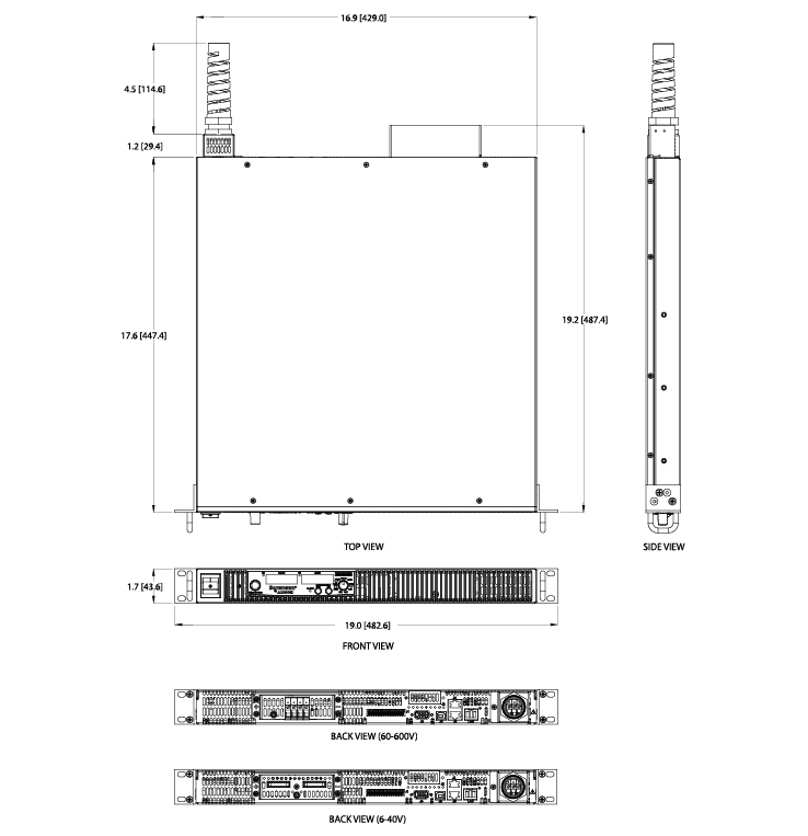
| Mechanical Specifications | |
| XG 1700 Watt (W×H×D) | 16.8 x 1.7 x 19.0 inch (429 x 43.6 x 483 mm without rack mount ears) |
| Weight | 22 lb (10 kg) |
| Cooling | Forced air cooling by internal fans |
| Regulatory Approvals | |
| Safety |
CSA 22.2 No. 61010-1, 60950-1-07 and UL61010-1, UL60950-1-(2nd Ed) 12 12. Marked with cCSAus, CE for EMC & low voltage directive |
| EMC | Complies with EN61326-1 Complies with EN55022, Class B, FCC Part 15B for conducted emissions Complies with EN55022, Class A, FCC Part 15A for radiated emissions Complies with EN61000-4 series of standards for immunity |
|
* Typical 1. Time for the output voltage to recover within 0.05% at its rated output for a load change 10-90% of rated ouput current. Output set point 10-100% 2. Double insulation on primary to secondary isolation barriers. Basic insulation primary to protective earth ground. 3. Current: 0.51 A minimum guaranteed, 0.72 A typically available. Overcurrent protection (each output) is automatic, non-latching. When OCP is tripped the aux voltage folds back and will recover to nominal condition when the over current condition is removed (typ. <0.2A). To protect external circuits attached to the aux outputs it is recommended that customers use an appropriately rated fuse in series with the aux outputs set point 10-100% Note: All specifications are subject to change. 구매, 기술, 렌탈 문의 이성종 과장 010-4812-3482 / sjlee3482@gmail.com | |
옵 션 사 항
- Isolated analog control (ISOL)
- GPIB interface Card
- Isolated analog control (ISOL)
- GPIB interface Card
- GPIB-Multichannel
- Ethernet interface Card
- Rack mount kit
- Ethernet interface Card
- Rack mount kit
구매, 기술, 렌탈 문의 이성종 과장 010-4812-3482 / sjlee3482@gmail.com
